
Fuel and engine data on a railway snowplow’s operator panel
How a railway machinery manufacturer put fuel consumption, tank level and engine data from a 100 kW generator onto its standard RS-485 operator panel — and made the setup part of its factory design.
A builder of locomotives and special rolling stock
A multi-profile engineering company that builds railway machinery, ventilation equipment and industrial machines. Its core business is locomotives and special rolling stock for railways and metro systems.
- 10 business areas
- 100+ employees
- 1,000 regular clients
The panel showed power — but not fuel or engine data
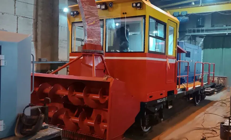
The auger-rotor snowplow clears large volumes of snow from the tracks: the auger gathers it and the rotor throws it clear. Both are driven by a hydraulic station powered by a dedicated 100 kW diesel generator with a 200-litre tank.
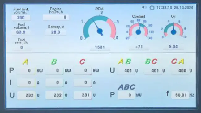
The operator watches the generator on a cab panel that receives voltages, currents, frequency and power over RS-485 (Modbus RTU). With standard equipment, though, the panel couldn’t show what matters most for running the generator: engine RPM, coolant temperature, oil pressure, battery voltage, instant fuel consumption and fuel left in the tank.
Sensors on one bus, converted to RS-485
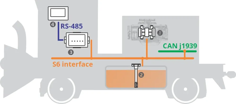
A DUT-E CAN fuel level sensor in the tank measures level and volume. A DFM D CAN differential flow meter in the supply and return lines measures instant consumption without modifying the fuel system. Both connect through an S6 cable system into one interface that also carries the generator’s CAN J1939 engine data.
A MasterCAN CAN2RS converter collects the J1939 messages and converts them to RS-485 for the operator panel.
The standard panel now shows live fuel consumption, fuel remaining, engine data and electrical output, so the operator can react to issues immediately. The manufacturer has written the converter, flow meter and fuel level sensor into its factory design documentation — new snowplows are equipped during production. Adding a telematics gateway later would send the same data to monitoring software for remote tracking, theft prevention and predictive maintenance.
Task → Solution → Result
Missing data on the panel
The operator panel had generator power data but no fuel or engine parameters.
DUT-E + DFM + MasterCAN CAN2RS
Fuel and J1939 engine data on one interface, converted to RS-485 Modbus.
Series fit
All parameters on the standard panel; equipment now in the factory design.
All the required equipment was delivered in a short time. … All necessary data from the diesel generator’s CAN bus was successfully converted into RS-485 messages. As an engineer, I’d like to highlight the quick installation and the ease of integrating all telematics components.
Lead specialist · Railway machinery manufacturer
Want product info and guidance from our experts?
Tell us about your fleet and we'll recommend the right measurement setup.